Structural form and technical requirements of marine crane slewing bearing
The marine slewing bearing is an important component of the ship deck crane, and its working safety and reliability are required to be very high. The key point of the slewing bearing of the port marine crane is low speed and high load capacity. According to the actual usage, the customer’s speed for marine products is 6-7 rpm. As the application field of slewing bearings continues to expand, its application capabilities in the ship field have also been well demonstrated.
一. Structural form of marine crane slewing support
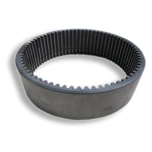
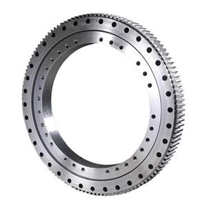
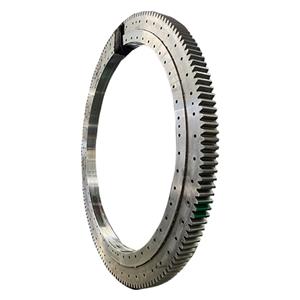
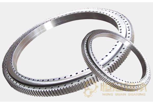
1. The slewing bearing is composed of rings (inner ring, outer ring, upper ring/lower ring), rolling elements, isolation blocks, sealing belts and oil cups.
2. Slewing bearings are divided into three types according to their structural types:
1) Single row four-point contact ball slewing bearing (01 series).
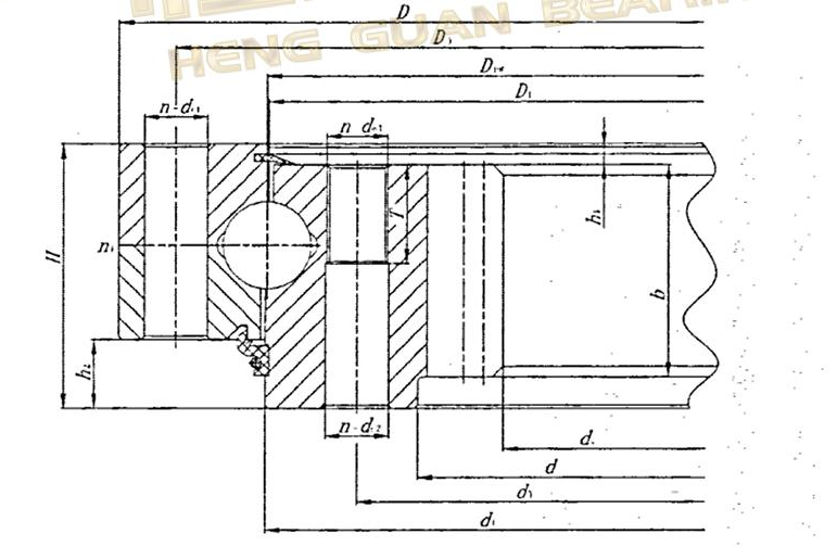
2) Double-row ball slewing bearings with different diameters (02 series), the nominal diameter combination of the rolling elements is upper row/lower row: 25/20, 30/25, 40/30, 50/40, 60/50.
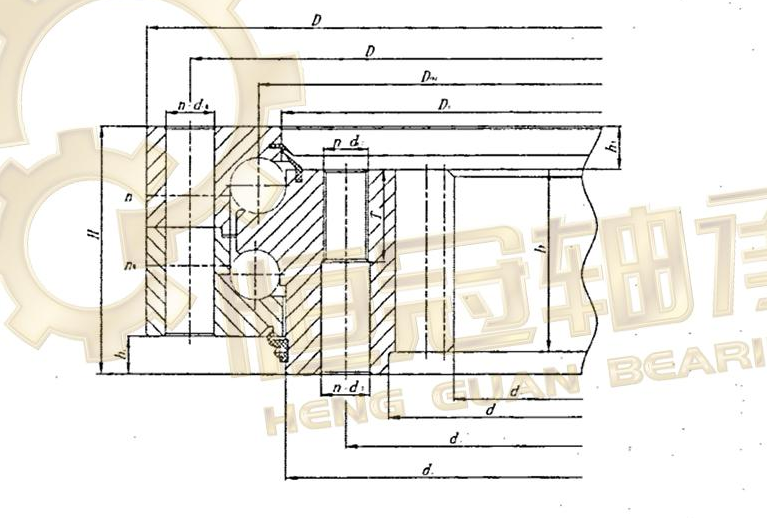
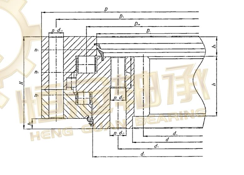
3) Three-row roller slewing bearing (13 series), the nominal diameter combination of the rolling elements is upper row/lower row/radial: 25/20/16, 32/25/20, 40/32/25, 45/ 32/25, 50/40/25.
3. The model representation method of the slewing bearing is as follows. If there are other codes after the pitch circle diameter of the rolling element group, its purpose code should be after.
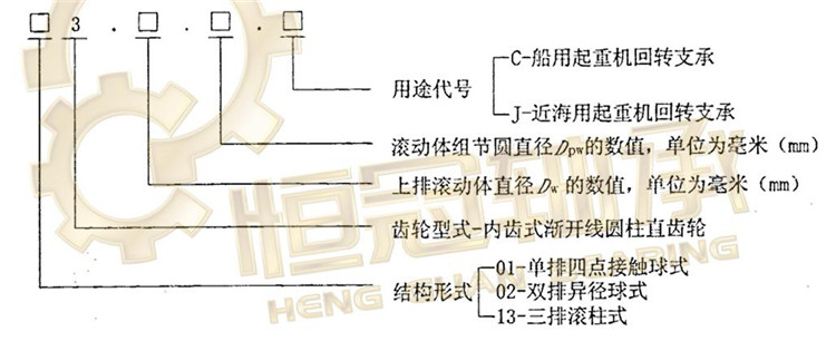
Marine three-row cylindrical roller internally toothed slewing bearing with an upper row of rolling elements with a diameter of 40mm and a rolling element group pitch circle diameter of 2500mm: Marine slewing bearing CB/T3669-2013133.40.2500.C
二. Technical requirements for marine crane slewing bearings
1. Rolling element
1) Steel balls should comply with the regulations of GB/T308-2002, and their tolerances should comply with the regulations in the table.

2) There should be no cracks on the raceway surface.
3) The slewing bearing forging blanks with a raceway center diameter of more than 2m (inclusive) should meet the requirements of GB/T6402-2008 3.
4) For the Charpy V impact absorbed energy of ferrule materials used in ordinary marine cranes, the average value should not be less than 25J at -10°C or TD, whichever is lower, and a single sample should not be less than 20J.
5) For the Charpy V impact absorbed energy test of ferrule materials for offshore cranes, the average value should not be less than 42J at -20°C or the lower value of TD-10, and a single sample should not be less than 27J.
6) The surface hardness of the surface quenched ferrule raceway should reach 55HRC ~ 63HRC, and the depth of the hardened layer (that is, the depth of the raceway surface with a hardness above 48HRC) Ds value should comply with the requirements in the table.

7) Soft belts are allowed after the raceway is quenched, and the requirements are as follows:
a) Soft belt width: For the soft belt width of ferrules without blocked holes, when Dw≤25mm, it should not be greater than the 2Dw value; when Dw>25mm, it should not be greater than 50mm. For ferrules with plugged holes, the width of the soft band should not be greater than the diameter of the plugged hole plus 35mm;
b) Soft belt mark: Except for the soft belt of the ferrule with a blocked hole, which should be set at the blocked part without marking, the other ferrules should have a permanent "S" mark on the non-installation matching position corresponding to the soft belt; for In addition to being marked as above, the soft straps of the double half ferrules should also be matched with the drilling and assembly so that the soft straps of the double half ferrules overlap the body.
3. Isolation block
The material of the isolation block should be made of polyamide 1010 resin specified in HG/T2349-1992. Other materials that meet the performance requirements can also be used.
4. Sealing tape
The material of the sealing tape should be made of SN7453 nitrile rubber that complies with the regulations of HG/T2811-1996. Other materials that meet the performance requirements can also be used.
5. Oil cup
The oil cup should be resistant to seawater corrosion.
6. Ferrule gear
1) The gear is an involute cylindrical spur gear, the radial displacement coefficient x is generally 0.5, and the crowning coefficient k is 0.2. Other displacement coefficients can also be used as needed.
2) The gear module should comply with the requirements of GB/T1357.
3) The accuracy of gears is generally 10 specified in GB/T10095.1-2008 and GB/T10095.2-2008.
