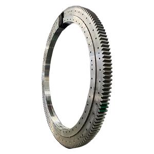
Considerations for slewing bearing selection
1. Load capacity
It is necessary to select a slewing bearing by comparing the loads and/or stresses associated with the intended application with the characteristics of known slewing bearings. This can be, as the case may be:
When there are no dimensional requirements, the best slewing bearing for this purpose will be selected based on the load requirements. When there are dimensional restrictions (diameter, module, weight, etc.), the suitability of the slewing bearing under consideration will be verified and its life will be calculated. The load curve is calculated based on the bearing capacity of the ring, which is the load shown on the coordinate axis, as a function of:
(1) its geometric shape,
(2) the type of steel used,
(3) heat treatment
(4) the type of rolling elements, etc.
(5) the contact parameters of the rolling elements
2. Graphical representation
The capacity of a slewing bearing is graphically represented by two basic curves:
(1) Limit curve (L)
- This curve shows the maximum capacity of the ring.
- The "limit" curve shows the maximum value that must never be exceeded, even in the case of test loads or occasional overloads.
(2) Utilization curve (U)
- This curve is derived from the maximum value. curve, representing the maximum permissible operating value for an application that only occasionally reaches this maximum load.
-Expected life: up to 50,000 cycles.
3. Slewing bearing application factors
In order to recommend a slewing bearing for a specific application, it is necessary to ensure the appropriate strength of the raceway by comparing the operating load with the capacity of the slewing bearing selected or to be determined. This comparison also gives you an idea of the service life of the slewing bearing. But the latter can only be calculated for the operating stresses, not for the accidental stresses caused by short-term and irregular overloads or equipment acceptance tests.
4. General formula
Given P represents the working load, where Px: axial load axis, origin Py: origin of the moment axis.
General formula: Px = Fa x (Ka x Kv x Kt)
Py = Mt x (Ka x Kv x Kt)
Use (Ka: utilization-factor, Ky: life adjustment factor, Kt: speed adjustment factor)

